Sunday, August 31, 2014

GONE TO POT

This is another one from RTC Chicago.  It's based on a picture of a chinese pot that I decided would be an interesting shape to model in Point World.

Once again we are lofting with loaded profile families, and the rig is a combination of "straight line" & "rectangle".


So we start with an octagon profile. There are different ways to set about this.  You can base it on points, 8 of them all spaced out equally from the centre with a parameter to control that distance.  Or you can dispense with the points and dimension directly to the lines.


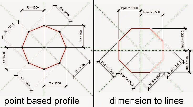
Turn this into a scalable profile with a simple formula.  R = input * Scale. ( I use R for consistency, because the simplest profile of all is a circle, radius R)


So we have a mass profile.  Load this into another mass family.  Draw a vertical reference line at the origin point. Host points on that line.  Reveal the normal reference planes.  Host instances of the profile on each of these, then play around with the input values so as to build up the shape of the chinese pot.


You need to select the profiles in groups and create form.  First 4 profiles, then 2, then 2 again, then 4 again.  Sometimes two forms share the same profile.  By the way I forgot to mention the height parameter.  And of course the profiles and the height are all linked to the same global scale factor.


At the top of the pot, there is a little pointed knob for lifting the lid off.  This is a revolve.  We could use a series of circular profiles, but I'm opting to illustrate a different technique.  Typically, the rectangular rig takes the form of a ladder.  So I'm building one of these off the top portion of the vertical line.  It involves hosting points on points and giving them an offset.


Create a loop using splines with 3d snapping.  Select this and the vertical line to create form.  Revit should interpret this as a revolve.


You can see that the 3 instances shown above vary in both height and slenderness.  Quite easy to set up. The scale parameter (used to control the nested profiles) is calculated from height & slenderness via a simple formula.


That's as far as I went for RTC, just a quick example in passing.  But of course we can take this further by loading different profiles.  The possibilities are endless, but here are a few.


One way to achieve this is via type-based profiles. This involves a bit of heavy lifting, with 9 different types needed for each profile.  The amount of work can be reduced somewhat if you base the new profile on a copy of the old one.  That way you don't have to set up all the named types again.


I followed this through to create a family with three types (octagon, circle & square) plus instance parameters to vary height and slenderness.

To get more value from my effort, I "saved as" 3 times and played around with the positions of the profiles and the relative size of the knob.  The result is a systematic exploration of variations in shape.  I'm not sure why anyone would want to have so many different pots to choose from, but just in case you do, this is one way to achieve that end.


Another approach, would be to use instance based profiles.  That's how my original pot was built because it's much faster to set up that way.  But when you swap out the profiles with a parameter all those instance values get lost and you end up with a shapeless extrusion.


Not to worry, you can just create another family for each shape.  Even better, rename the profile in the new family to match the name of the profile you want to load.

I followed this approach to create families based on profiles incorporating my famous "bulge factor" parameter.  This dates back to my Doric Pumpkin experiments and uses a points-based profile.


The "bulge factor" will take you all the way from very concave to very convex.  I didn't do "very concave" in this example because it doesn't look right in a pot.


The nice thing about this kind of exercise is the way it reverses the diminishing returns principle.  Once you've done the initial work, adding a new profile takes very little effort.  Also varying the relative heights of the different sections is easy and before you know it you have dozens, if not hundreds of variations.


So just remember, these families belong to the mass category.  Other than that, they behave nicely.  If you want to play with them, follow the download link.

GET YOUR POT HERE


Tuesday, August 26, 2014

THE UNIVERSAL LOLLIPOP TREE

This is something that I developed for my Urban Design explorations talk at RTC Chicago.  The idea was to take the basic "blob on a stick" tree that is often used at an Urban scale, and make it more parametric.  Hence the universal lollipop tree.


It wasn't too hard to set up.  A revolve made from quarter ellipses.  You can vary the shape by moving the "waist" up and down, also by changing the proportion of width to height.


The family I used in my presentation looked fine in the images, but in reality was less than perfect.  The way I had hooked up the parameters led to somewhat counter-intuitive behaviour.  For example, increasing the trunk height factor would actually decrease the proportion of trunk to canopy.


So this weekend I decided to fix that family, make it more user friendly, and offer it up to the general public.  Version 2 was much better.


There are subtle changes to the formulae that make them work more as you would expect from the given names.  I set up 15 types, with names that I thought would be easier to follow.


That's all good, but the names really refer to shapes.  At one point I was actually adding the height to the type name, but this just seemed to make things more complicated.


I decided to go for a version 3 where height would become an instance parameter.  You probably know that the different family templates have slightly different behaviours baked into them.  The Planting Template has a "Height" parameter that you can't delete and you can't change to "Instance"  So I had to resort to creating a new parameter named "_Height"


Because all the "driven" values are ultimately dependent on "_Height" these also have to be instance parameters.  Revit won't let you have two instances of the same type with different Type Parameters (which is what could happen if you allow a Type Parameter to be dependent on an Instance Parameter)

Because of the way the parameters are all interconnected, I had to delete all the formulae (copy-paste them into a text document) change the parameters to instance, then copy all the formulae back in.


The end result is a tree whose shape is determined by four type parameters, and whose height is controlled by a single instance parameter.  There are a bunch of greyed out "formula driven" parameters that appear in the "other" section of instance parameters.  These record the actual dimensions of any given family instance.


So that what I decided to do with my lollipop.  You can probably get by with the 15 types built into the family, but it's quite easy to tweak them, if so desired.

Hope you like it.  Download from here.

LOLLIPOP TREE DOWNLOAD

Monday, August 18, 2014

OUTER SPACE

When I was looking for everyday objects to model in point world (for my RTC presentation in Chicago) one of the first pieces of furniture that sprang to mind was the Space chair.  A Fritz Hansen original, much copied, classic use of moulded plastic sheet.


For the longest time I couldn't figure out how to make it.  I kept trying to see the form as a series of profiles hosted on a spline, but that turned out to be really clumsy.


Then one day the penny dropped.  Actually you don't need Point World.  The underlying form is a blend.  It's like one of those thached roofs that are round at both ends with a straight ridge in the middle.


Flip that upside down, at an angle.  Make a similar void, slightler smaller, cut away and you've got it.


Well it needs to be trimmed around the edges of course, but that shouldn't be too hard.  So I started with a profile.


The swept blend was a wonderful thing when it was first released, then a year later it got overshadowed by Point World and I've been neglecting it ever since.  First insight.  You can do a swept blend with a straight line.  Why bother ?  Because it allows you to use loaded profiles, something that ordinary blends don't accommodate (perhaps they should)


Using a straight line as the path for a swept blend gives me lots of control, easy to adjust the length and angle.  The profiles are parametric, easy to adjust their sizes and proportions.  I was using a CAD download from Fritz Hansen as a guide to get the size & shape right.


My first attempt to trim the edges was awful.  Second go was much better, but you can still see sharp edges when you zoom in close.


I decided that I needed a void blend.  Now you can make a void extrusion with a hole in the middle, but that won't work with a blend.  You can only have one closed loop at each end.  No donuts allowed  ... unless you leave a little sliver of a gap somewhere so that actually it's just one loop.


That's what I opted to do.  Not very elegant, but it works.  I leaves you with a spike of plastic sticking out sideways as if the shape had been injection moulded rather than pressed from sheet, but with care you can clip this off so that it's barely noticeable.


Now for the cushions.  I had a quick go at making these in Vanilla also, but it was never going to work, so I'm back in point world after all.  I isolated the cad object for the cushions.  It's a mesh.  Maybe some of you know how to convert this into a solid that will come into Revit and explode nicely.  That would save time, but I've never figured that one out, so I'm going to make if from a series of profiles ... in Point World.


I decided to set up a series of reference planes that slice through a cushion.  They don't actually cut it of course, but I can host splines on these planes and adjust them until they are pretty much sitting on the surface.  A bit tedious, but it was an interesting exercise.


I'm using conventional 2d splines here, the kind that stay resolutely on the reference plane you put them on.  So the only ref points belong to the straight lines that are used to close the loops using 3d snapping.


Use create form on the first 2 or 3 loops. Then progressively add more to create a reasonably convincing replicat of the CAD cushion.


You can easily see where your surface is proud of the original and where it dips below.  Select the nearest spline, look for a node, adjust to your heart's content.


There's always going to be a flat end where your last profile sits, but you can make this very small, or you can just decide that it's not going to show up, especially if the cushions are black, which they often are.


When exporting to cad from a family, your temporary hide/isolate settings are respected, so it's easy to push this out as an SAT solid.  Open this in autocad and you get a chance to round off the sharp edges.


Import SAT back into Revit and explode.  Now it's free-form native geometry and you can apply a material parameter.

The base is pretty straightforward to make so I won't go into much detail.  It helps to set up a ref plane with a parallel section plane when creating the extrusions for the legs and the revolves at the end where they attach to the plastic.


You might think that this results in a heavyweight family, but it's just over 1mb.  I'm not going to spray hundreds of these around anyway. There are a masking regions and symbolic lines to represent the object in plan views.  Interesting to note that the "free form element" for the cushions doesn't trigger a "visibility settings" button on the ribbon.  Fortunately you can turn it off in plan views via the "Visibility/Graphics Overrides" in the properties dialogue.  Another case of inconsistent terminology for Steve Stafford's record book.


I've turned all the 3d geometry off in orthographic views and at coarse detail level.  That should handle most performance issues


For the front & side elevations I used the CAD objects kindly provided by Fritz Hansen.  Just added a masking region.


Hope you found that interesting.  Download the family here


.Space Chair Download


I'm going to finish with a gag reel that illustrates the follies of cleverness.  More failed attempts to create the space chair using Point World gymnastics.


Along the way I developed the most complex trigonometric formula I have ever devised for Revit. (not saying much)  But none of the results lived up to expectations.  What a waste of effort.


Or maybe not.  Sometimes the simple solution will only come to mind after a long & difficult search.


Sunday, August 10, 2014

CURTAINS THAT FLEX

In my second presentation in Chicago last month I proposed a heirarchy of 3 major types of rig for use in point world: straight line, rectangle & box. 


The series of planters by Frank Lloyd Wright that featured in recent posts were all based on the Straight Line Rig, hosting a series of profiles.  In this post I will use the Box Rig to make families that represent curtains.  The aim is to achieve something approaching the softness and irregularity of real-life drapes.


We start with a rectangle, drawn in plan, using reference lines.  Add equalisation plus parameters for Width and Depth.  Select the rectangle and creat form.  Convert the offset into a Height parameter.  Sometimes it is useful to add formulae that make Height and Depth dependant on the Width, as in the image above.  For the curtains we will keep things simple and type the 3 dimensions in directly.


Make your box 3m high, 1200 wide, and 200 deep.  That will be a reasonable starting point for a curtain that is partly open.  For my RTC presentation, I simply drew 2 splines using Spline through Points with 3d snapping on: one spline along the top face, another along the bottom face.  The points will snap to the edges and acquire NCP parameters (values between 0 & 1 which control their position as the family flexes)  Select both splines and create form.  Add a material parameter.   The result is an undulating surface: moderately successful, but a bit too stiff.


So I decided to add a reference line along the top face, and another along the bottom.  This allows me to vary the depth of the troughs and valleys in a somewhat random manner and create curtains that look more natural, with irregular folds.


Flushed with success, I explored the possibility of even more dramatic ripples with 2 points for each fold in the cloth.  This seemed to work OK but for some reason when you go to a camera view, random lines show up, criss-crossing the scene.  They look worse on screen than in an exported image, but still rather disconcerting.


No worries, I can live with my second version.  Copy this and change the width and depth (wider and more shallow)  Create a new type and apply a new material.  Mine is based on the Bamboo that comes with Revit, but enlarging the scale and fading the image so that it simulates a sun filter material.  Now we have 2 layers of drapes. 


Check out a plan view.  You get some very interesting shapes, but not what you would want in a set of drawings. 


Building plans are stylised.  Sometimes we forget that, but it's the main reason for the "symbolic" capabilities of Family Editor.  Hide the solid geometry of your door panel, and add symbolic representation of a "door swing".  Sadly this feature is missing from Point World.


We had some very interesting discussions in one of Paul Aubin's sessions at RTC, effectively a dialogue with Autodesk at a fairly senior level.  One of the ideas that came up was to have a new family template, possibly called "Generic Model CME", which behaves like a standard Generic Model family, but uses Point World techniques for making geometry.  It would have the visibility controls shown above, plus Symbolic Lines, Masking Regions & Detail Items. 


You would be able to go to family categories and swap to just about any category you wanted, including plumbing fixtures.  It would not be based on adpative points, so the family would respond to the "Level" and "Offset" instance parameters just like a normal Generic Model and you could schedule the components by level.  Even better, you would be able to nest this type of family within a hosted template.  So you could have a wall mounted light fitting based on Point World geometry.  We don't know yet whether this is a realistic request.  Perhaps the coding would just get too messy.  But it would be a wonderful thing if the factory discovered that it was able to grant us this wish.


In the meantime we will resort to work arounds.  Here is one.  New family, Generic Model.  In the plan view, set up reference planes, parameters and symbolic lines as shown below.  Nest this family into another Generic Model.  Create an array, link parameters and "hey presto" we have symbolic representation of a curtain inside a Generic Model family (not a detail item) 


This is good news because we can nest a GM into Point World.  So load it into your curtain, place it ina plan view, lock the bottom left corner to the same corner of the box.  Now you can link up the parameters.  You'll need to set up a formula in the curtain family to generate an "X" value based on Width and No of folds.  If you do this correctly, you will have a symbolic representation of a curtain that flexes correctly and only shows up in plan views.


How do we hide the 3d geometry in plan ?  I made a new sub-category called "adaptive 3d"  (my curtain family was made from the Generic Model Adaptive template.  In many ways it would have been better to start from "Conceptual Mass")  So assign the curtain geometry to that new sub-category, and in the project you can turn the sub-category off in plan views.  If you use a view template, it's not too painful.


Why do I say that the "Mass" template would be better than "Adaptive" for this kind of family ?  Well Adaptive Components don't respond to Levels & Offsets the way that other families do.  They're not meant to.  Adaptives are supposed to attach themselves to points within the project and adapt their size and shape accordingly.  They don't have an origin in the same way as normal families.  They are Shape Shifters.  They don't belong to any particular level.  They define themselves in relation to other objects, not to some absolute datum.  So if you want to control the position of your family by selecting a level and typing in an offset, Adpative Components will disappoint you. They also have a disconcerting tendency to flip upside down when mirrored.

So my freebie is slightly different from the above story.  It's a mass family, the symbolic "worm" is centred about the origin (which usually is a more stable way to make families) and the subcategory for turning things off is called "_Hide in Plan"

Check it out for yourself at this link.

Mass Curtains.rfa