Tuesday, March 26, 2013

PULL THAT LEVER

This weekend I was continuing my preparations for RTC Auckland, revisiting the work I did on Lever House quite a long time ago.  My presentation aims to make comparisons between Lever House, Casa del Fascio & the Gherkin.  In the process I hope to demonstrate the value of a BIM approach to the research & teaching of architectural subjects (history, technology, design theory etc etc)


By coincidence I received a request a few days ago from Vincent, (a French student) asking me to share my files for Lever House.  They are doing a project of some kind.


So I've decided to upload some work-in-progress files for whoever is interested, but especially for young students of architecture & other construction disciplines who may want to gain a deeper understanding of some of the key moments in our history than can be gained from the usual slide lecture approach that we experienced in our university days.


The images are snapshots from these files and represent the state of play as of last night. 


A word of warning here.  It's all a bit rough at the edges.  Need another weekend at least to have this model ready for Auckland.  Also I am working from incomplete data and one brief site visit a few years ago.  I have had to make many assumptions and some judicious simplifications.  The aim here is to understand principles and generate useful ideas, not to create a dusty museum specimen of some arbitrary moment of frozen time.


I firmly believe that BIM software opens up the possibility of an exchange of ideas and information about our built past. far beyond anything currently available.  Think google earth/street view, but with the ability to walk inside listed buildings and access analytical diagrams, learn about the people involved, see exploded diagrams of construction details.


I have uploaded 2 pdf files with several sheets each, & two 3d dwf files.  One of the whole building and the other a deconstructed portion of the external skin.  The work is incomplete, but I hope it will be useful.  You can find the files  HERE  Lever House

Sunday, March 24, 2013

CURVE THAT SCREEN

Thanks to Dave Baldacchino for pointing out my blind spot.  (see comments on previous post)  My take on the Voysey style stair screen is much more easily achieved using a curtain wall & edit wall profile.


Which got me to thinking if there were any advantages to the adaptive component approach.  What if you wanted to curve the screen.  Not possible to edit profile on a curved wall.


But of course you could make an in-place mass & do a "curtain system by face".  But now we are approaching a situation where it's almost as much effort as making an adaptive family.  And once you have made the family it's easy to play with different parameter values.  Design by flexing ... appropriate if you have a vague concept and want to explore the possibilities.


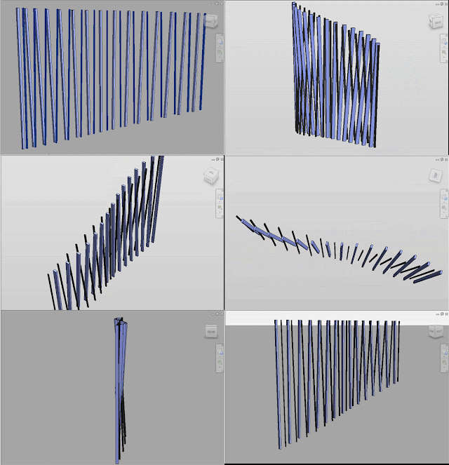
Once I got started on "S" curves I couldn't resist setting up an alternating pattern.  Now we are entering territory where curtain walls struggle.  I'm not going to do a step-by-step on this.  It's an extension of the principles from the previous post, but with a bit of "host by intersection" thrown into the mix.


The possibilities are pretty much endless.  Not sure what the application would be, starting to feel more like Calatrava than Voysey now.  Also looks like some kind of drunken bar code.


It's difficult to grasp the geometry fully based on single frames.  It could be a screen or a ceiling baffle in an up-market food court perhaps.  I've seen crazier forms.  The excitement would be in the changing patterns as you walk past. 


Using a different colour and size for the two repeaters makes it easier to understand, which is why I did that.  Then I realised that alternating mullion types would be another justification for  the adaptive approach, even on a straight screen.  You could do it with a curtain wall, but it starts to get messy, especially if you want to go through several design iterations.


I'm going to finish up with a little GIF to simulate the effect of movement. And thanks again to Dave for making me think harder about what I am doing and why I might want to do it in a certain way.


Thursday, March 21, 2013

PRIMAL SCREEN

This week Matthew, an intern in our office who has been using Revit for some time, came up with an interesting query.  He wanted to make a slatted timber screen that acts as a guarding to an open staircase.  He had made a rectangular version based on a parametric array & a sloping version based on fixed geometry.  But how to make a parametric sloping version ?  This is what he wanted to achieve.

I ad-libbed my way to a solution based on adaptive components in about 20 minutes as a live demo sitting down at his computer.  Basically it went like this.  "New Family" choose "Generic Model Adaptive".  Place 2 points and make them adaptive.


Select the points and hit "spline through points". Turn this line into a reference line (check box under properties)  Place 2 more points, hosted on the line. one close to each end.  We will move them right to the ends later, but for the moment don't want to get them confused with the adaptive points.

Now create a new mass family.  Go into the plan view & draw a rectangle.  Add parameters for X & Y dimensions.  This will act as a profile within the massing environment.  Load it into your adaptive family & place and instance on the reference plane of one of the points.


Do the same for the other point.  Now you have 2 profiles hosted on a reference line.  Select these and hit "create form".  You end up with a rectangular slat that will adapt its length to whatever is constraining the two ends (ie whatever the two adaptive points are connected to)


All good.  But in case you had a problem with the alignment of your profiles, don't forget about the Work Plane Viewer.


Once everything looks OK you can move the points to the very ends of the reference line.  Just select each in turn and check out their properties.  Under "normalised curve parameter" you will see a value between 0 & 1.  Adjust these to be exactly 0 & 1 respectively.  The crazy parameter name really means "position along the line"  (don't worry about it, it does make sense once you get to understand the full possibilities)


Create another new family.  Could be "generic model adaptive" or "conceptual mass"  (I think)  Set up dimensioned ref planes as shown.  I did this in a front elevation view.  Place 4 reference points and lock them in both directions to the planes.  (Use the align command & close the padlocks that appear)


Just check that everything works.  Type in new values for each parameter & watch the points respond.  If they don't follow the ref planes, try locking them again.  Now you can use "spline through points" again to create a horizintal ref line & a sloping ref line.  We're almost there.


Select the lines & choose "divide path".  You'll get 6 nodes.  Do this for both lines.  At this stage each line has become 2 things at once: the original ref line AND a divided path.  You can use the tab key to toggle between these two personalities.  The divided path has a "number of nodes" property.  You can hit the little secret button at the end of the line to link this to a parameter.  I created one called "no of slats" because I'm going to load my 2 point adaptive family and attach it to these nodes.


When you select this slat, a little "repeat" button will appear on the ribbon.  Hit this and it will populate the repeaters.  That's it.  We have an adaptive family with 3 dimension parameters to control the shape, and a "no of slats" parameter to control ... the no of slats.


Try different values to check that everything works.  This is called "flexing" the family.


And my final image shows the parameters that are available.  I already mentioned the ones in the host family, but you also have 2 dimensions and a material in the slat family.  (I forgot to mention creating the material parameter ... you just select the form and hit the little secret button at the far end of the material field under properties)  Hope someone finds this useful. 

You can download a copy of the family from here:   SCREEN.RFA


Wednesday, March 6, 2013

SURFACE EFFECTS

This is an experiment

 
That was hand written shortly after I typed the following notes on my Surface


The surface camera is struggling with hand-written text in poor light, so I have re-typed the next bit of the story.


In the earlier one-note session I had drawn a diagram.
(PIS = product information system)  (DIC = digitally informed construction)


The hand-written page was interrupted by breakfast. I got as far as this.


The Surface is becoming a useful tool for catching early morning & late night thoughts while they are fresh in memory.  I like it a lot & enjoy the ease of transferring files to & from my laptop. 


That was my desk soon after arriving at work.  The experiment is some kind of "reality TV post".  Just throwing bits and pieces of my thoughts at you in the raw form that I captured them in.  Here is the view from the back of the surface while it sits on my desk.  The orange cupboards are full of project files.  So much for the paperless office.

 
So I have this idea that the "single building model" is great for designers (drawing-ers as they say in France) but only part of the story for builders & suppliers, who can certainly use the model, but don't spend their waking hours MAKING models.  So perhaps the classic "spokes of a wheel diagram" is not the full story.  Hence my "love triangle"   I can hear some of you saying, yes put that is the traditional process, we need a new process (IPD etc etc)  Fine.  But firstly many of us are stuck with the traditional process for some years yet & we need to find ways of involving suppliers & contractors in our BIM process.  Secondly even with IPD, most of the suppliers will be outside the Integrated Design & Build team, and there will still be a subtle shift of roles when the project moves from "drawing board" to site.  Perhaps the diagram will be more of a T square than a Triangle.


So I am just thinking aloud, don't get too stressed, but perhaps we are trying too hard to shoehorn everything into the BIM box.  BIM is Building Information Modelling.  You are making a virtual 3d building with intelligence.  So you can do that with Archicad or Revit.  It's an extension of the long & extremely worthy tradition of visual thinking (drawing/design)  People talk about BIG BIM, meaning that "BIM for desiging with" starts to suggest ways that other activities in the world of construction might also change.  So you get terms like "field BIM", "5d BIM" ... (not sure why field BIM isn't called 6d BIM :-)  No problem.  People like Newforma have been a bit bolder and labelled their processes PIM (Project Information Management)   We even find people referring to "BIM authoring" to distinguish this part of the process from "BIM collaboration" or "BIM costing"   I can't help thinking, what's the difference between BIM authoring and BIM modelling ? 

Just stand back for a second.  We have drawing tools, costing tools, filing tools, programming tools.  We used to do this stuff manually, now we have digital processes that transform the way we work (like letters & email).  What we are struggling with a bit is getting everything to work nicely together.  I have been guilty of banging away at suppliers, "you need to get on the BIM train, you're out of date, why aren't there any Revit families on your website ?"  Fair enough, but perhaps we should also be listening to them.  Don't you think they have their own digital revolution going on ?  They have web sites where you can interact with their products.  Do we have web sites where you can interact with our buildings ?  Well maybe, sort of, but they tend to be glorified FTPs. Can an ironmongery supplier get on to our web site and populate our building with door hardware interactively ?

By and large we have managed to sell the idea that BIM is the catch-all phrase for where we are heading as an industry.  But it's a term that originated as a description of software for architects.  Applied to what engineers to it works fairly well.  Applied to what Quantity Surveyors do ... yeah maybe ... financial modelling perhaps.  Applied to what contractors do, document controllers do, materials suppliers & product manufacturers do ? ... not so sure.  BIM is becoming a term that is so all-encompassing and generalised that it starts to lose it's freshness & vitality.  Just look at some of the definitions out there.

Perhaps the design team should be saying "this is what we do. We called it BIM because we build an intelligent model of the building inside our computers.  We can give you access to this model.  We could even let you fiddle with some parts of it.  What tools & processes have you developed ?  How do they work ?  What do you like to call them ?  How could we imagine these systems talking to each other ? "

In short: maybe we should be listening more and shouting less.

Tuesday, March 5, 2013

SNEAKY FASCIST PEEK

I spent the weekend preparing for RTC Australasia.  Looking forward to spending 2 or 3 weeks in Auckland, visiting my sister, seeing the sights & attending RTC.  I will be taking two classes.  One will focus on conceptual massing, including my various pumpkin experiments.  The second will explore the use of BIM as a research tool for better understanding the way buildings work. 

I have decided to take 3 office buildings which happen to also be seminal works of architecture and use Revit models to dig deep .... I had started to model all 3 of these at one time or another and have previously posted about 2 of them.  I recently picked up a new book about Casa del Fascio and decided to start again and model it from scratch.  This was a good exercise in how far you can get in one weekend, and as usual I came up with some new ideas along the way. 

Of late my mind has been focussed on the use of BIM for concept design.  This is quite a complex building and I wanted to start by "roughing it out", sort of an analogy to the way sculptors often work.  I figured out the grids & levels, placed columns & floors, blocked out the main form with some chunky walls.


The architecture is all about expressing the concrete frame & playing games with subtle displacements and variations.  The facades can be seen as a matrix of cells.  I wanted to colour code groups of cells to create a simplified diagram of how the 4 different facades relate to each other.  It struck me that one way to do this would be to create a monster curtain wall family with 400x400 mullions spaced 4m apart and infilled with my chunky wall.


Duplicate the wall family to create types with different colours.  Select panels along vertical rows, unpin, and swap them out.  Use the empty system panel where appropriate.  This worked fine and helped me to get to grips with the underlying logic of the building.  It's a 4 sided courtyard (obvious references to the Renaissance Palazzo) but also can be read as two blocks of accommodation (left & right sides) with less substantial links at front & back.  As the modelling developed further the complexity of the form began to emerge.  The sectionalised perspective below illustrates this quite well.


You can see the games that he plays.  Reveal the frame, then hide it.  Walls of different opacities (and shininess).  The central volume has a symbolic & ceremonial importance.  Terragni believed that the Fascist party of Italy was an expression of the peoples will.  The building expresses the idea of a party born out of a revolution and the importance of transparency in its relation to the people of Como.  With the benefit of hindsight we can see that things didn't quite work out like that.  But I confess to a little admiration for the courage of Terragni's vision & hope.  There have been several popular revolutions across the middle east in recent times, one of them in a former Italian colony.  All of them are struggling to convert the fire of popular revolt into a lasting framework of peace & respect for all.  Not easy.


I didn't want to destroy my initial roughing out work, so I stumbled across an idea.  Why not use phasing to represent the different design stages ?  I created phases for Concept, Schematic & Detailed design.  The curtain wall version of the exterior facade belongs to Concept Stage & is demolished at the transition to Schematic.  New walls are built and window families developed to take us through to Detailed Design.

As a prelude to building the window families I drafted over the elevation views, making a detail group for each window type.  By copy-pasting these groups to a drafting view I could dimension them up to create an accurate guide for setting up the family geometry.


By duplicating views and assigning phases & filters appropriately I can keep simplified abstractions of my design alive while continuing to work out the finer details.  This approach certainly has widespread application to the kind of research work that I love to do.  I'm not sure how useful it will be for new design & build projects, but it's worth considering.


In just a day and a half, I have already created plans of this building that bear comparison with anything I have come across over the years.  It doesn't take long to find inaccuracies and contradictions in text-book drawings once you start to create a BIM model.  That's not really a criticism.  Most book illustrations serve their purpose of supplementing a text and giving readers images that can be used to compare the plan forms of different buildings.  But I think it is high time that we started to see histories of architecture & construction based on BIM models.  (a perfectly valid term in my view)


I need at least one more weekend to reach the level of detail that I need for my presentation in May, and this is only a sneak peek after all.  Don't want to spoil all the fun for my audience.  But as you can see, I did manage a reasonable image of at least one of the facades.  Those with sharp eyesight will notice that the window transomes don't align perfectly.  Actually the windows are very interesting, sort of a modern version of what the English would call "sash windows".  But I haven't modelled this properly yet.  Perhaps I will have different families for Schematic & Detailed Design.  Come to Auckland in May and find out !