Sunday, September 30, 2012

FANLIGHT FANNY

George Formby ".. the frowsy night club queen."  Things are not always what they seem.  I thought this was a view range problem.  Then I thought it was behaviour hard-wired into window families.  Then I figured it out.  There's probably a post about this somewhere on Steve Stafford's blog.  It falls into his category of inconsistent behaviours.


I have a lot of new users at present & have been setting up window families that they can edit themselves, basically non-parametric.  They are based on extrusions drawn in an elevation view.  Easy to create all kinds of glazing patterns as fixed-size windows. 


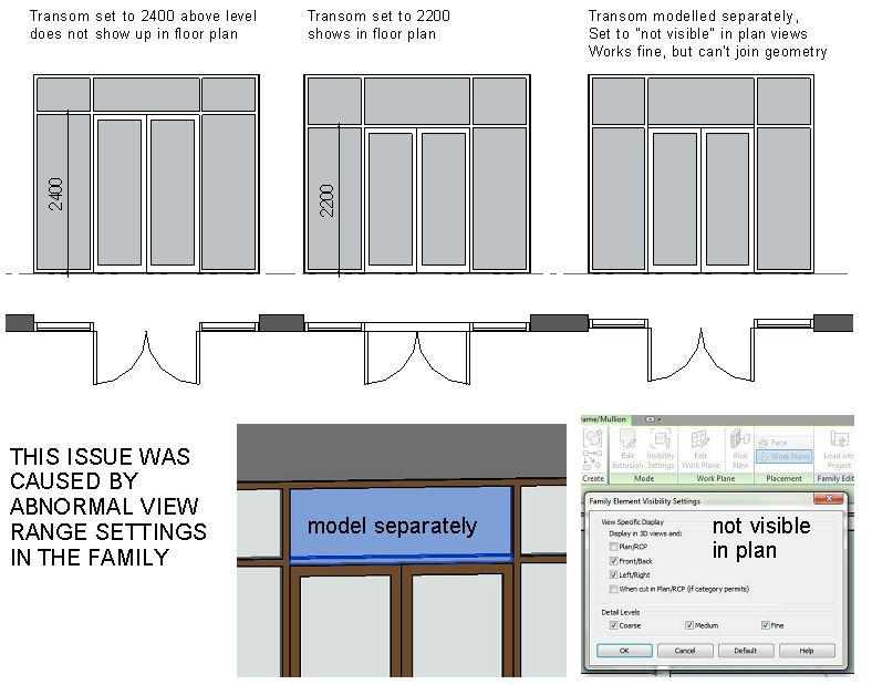
Today we needed to add doors to some of the ground floor openings, so I did a demo on this and it all went fine.  Later on I decided to make a parametric version & as I was flexing it the transom over the doorway came into view on plan. 


I experimented with view range: no joy.  Seemed like the only thing that mattered was whether the offending geometry was 2400 above the host level.  Spent some time charging down this blind alley & figuring out solutions based on visibility settings.  (hide in plan view, etc)  Then I found another family that was exempt from this problem.  For a moment I thought it might be something to do with sweeps and extrusions.  So I set up a little trial based on a new blank file and a new blank window family. 


Once again odd behaviour cropped up, but the values were different.  Now the family was fixated on a 1m cut plane regardless of what I did in the project.  Bells began to ring.  I've met this before.  Cutting behaviour depends on the view range in the family, not the project.  Checked it out and bingo.  My first problem family had a cut plane set to 2400 and the second was set to 1000.  I suppose this is sometimes useful, but it can also be very confusing.


Just for a laugh I opened up various wall-based templates.  Surprise, surprise ... lots of little differences.  Maybe there are good reasons, maybe it's just like our office content library ... work in progress, don't find time to make everything perfectly consistent. Windows have a default cut plane of 1000, projects and most other categories 1200.  I haven't checked the imperial stuff.  Top of primary range also varies quite a bit.  What does the top range in the family actually do I wonder ?


I do believe that more consistency would be very good, but I'm not sure it will be easy to come by.  I try very hard with my own work, but sadly I seem to be a human being.  Maybe I'll figure it all out one day.

Wednesday, September 26, 2012

FACTORY BASHING

There is something fascinating about the psychology of hardcore Revit users hammering away at Autodesk for being stupid.  We all have our gripes and out pet theories, but in the end, if you have chosen this tool above all others, surely you have to believe that the people making it are ahead of the game.  Otherwise there would be some cleverer people out there making a better tool.


One example that comes to mind is all the spleen venting that occured when the ribbon interface first appeared.  Say what you like about the 2010 version being flawed, the long term strategy has worked.  The dust has settled, the factory held their nerve, and the ribbon is here to stay.  With hindsight you can see how it fits into the longer time drive towards suites of products that play nicely together.  I certainly enjoy the fact that Revit, Acad & Navis all have a similar look and feel.
The latest controversy relates to Revit LT.  I stumbled across all this vitriol almost by accident.  What larks, pip !  You might have thought ... "if you like it buy it, if not, ignore it".  Seems not to be the case.  It's quite possible that this will turn out to be a big flop for Autodesk.  But I suspect not.  These days you need to buy BDS premium to hedge your bets and have both Acad & Revit on your machine.  Doesn't come cheap.  So you can see why the idea of mixing in a few cheaper licences crops up. 


Not everyone needs all the features all of the time.  At both ends of the scale there are people who could easily manage with a reduced tool kit:  senior management people who only have time to dabble;  guys who sit making window types all day long: people who spend two thirds of their time on building sites.  Maybe it will be a huge disaster as some predict, but I suspect that it's a gamble worth taking.   We might even take a few licences ourselves some time next year.  We will always have guys who spend most of their time using other tools (pencils, photoshop, excel, outlook, the telephone ...)  It would be nice if they could paddle in the shallow end of the BIM pool for a few hours a week. 


Two question remain.  "Shouldn't they have made full Revit available at half price instead ?"  Let me see now.  Why not just make it free ?  Let's have a more serious question.  "Did they choose the right features to omit ?"  Happen they did, happen they didn't.  Perhaps the mix will change as the product evolves.  Do I know for sure that they have made really stupid choices ?  Come on guys, it's nice to be young and cocky, but sometimes I'm glad to be the old fart who smiles enigmatically and waves his arms around in an ambiguous manner.

Tuesday, September 25, 2012

MORE WEB WEAVING

Episode 3 of my current bout of mashrabiya bending exploits.  This one is even more like a spiders web.


I started once more with some drafting to clarify the basic geometry and express it as fractional placements along the edges of a rectangle.


This informs a curtain panel by pattern, to set the positions for placing points (using the infamous "normalised curve parameter" which is an inherent property of points that are hosted on lines in the conceptual massing environment.  Pairs of points are then connected together using spline by points.


More points added and "hosted by intersection" so that they remember their relationship to two lines, even when these lines cross "at a distance" when the panel gets twisted.  All part of the magical points-based geometry that was incorporated into Revit from 2010 onwards.


Connect these in pairs to define the major pattern elements.  Create surfaces and sweeps.


Load the panel into a project then use it on some wiggly divided surfaces.  And that's another one done.  Took about 3 hours this evening after work.

And on the subject of points based geometry, check out Zach Krons video from a webinar he did recently.  From Data to Tada   I watched this last night and it just joined all the dots together nicely for me. I hadn't full understood the different point placement modes before.  Very nicely explained.

Tuesday, September 18, 2012

PATTERNISING WITH THE NATIVES

This post was nudged into being by viewer response.  A couple of comments on my last post with links attached.  Don't know if/when I will ever get around to Rhino/Grasshopper.  I think in the end you have to make a judgement call about where to focus your energies and for me it's less about clever modelling and more about exploring the intersection of ideas. 


The link to islamic patterns didn't really show me anything new, but it did supply the extra impetus to try harder to apply some of these geometries to PBP (Panel by Pattern).  The one I chose has a fairly simple rectangular repeat, roughly in a 5x3 proportion.


A little drafting work on top of a jpeg image gave me some useable spacings for points that can be used to generate a grid. 

There is a lot of hosting points on lines, selecting two at a time, & creating spline by points.  After a while you need to start using host by intersection, again repeatedly.  Eventually I have pieces of reference line that sit on top of the grid and will be used as paths to sweep along a tubular framework.


This involves lots & lots of host point, show reference plane always, set plane, draw circle, make radius a real dimension, apply a parameter.  After a few of these, I discovered that you can copy the assembly of point-circle-dimension into empty space and then rehost the point on a different line.  That's a big time-saver.


Eventually I have a curtain panel that looks like this, which should be testable.


Create an undulating surface as an in-place mass. 


Divide it so that the grid is rectangular in roughly the right proportions, load up the panel and amazingly it worked. 


Definitely worth doing a few more of these.  Took a couple of hours to create the panel, but if I make 3 or 4 of them and put them up for download maybe someone else will pick up the challenge and create a couple.

About half way through I picked up from my stats page that there was traffic coming from Revit Forum.  Following the link I discover people are enjoying my recent posts which supplied the extra motivation to finish off this post.  Sadly the original topic related to another Dubai based firm which has has a failure of nerve in relation to BIM.  Please don't be discouraged.  It's taken me 7 years of grinding away to get to where we are now at GAJ; multiple setbacks, hearbreaks, "is it all worth its".  Fortunately my principal has been very supportive, but it's been hard work with some of the other seniors.  Happy to say that we are now well past the point of no return and I have the pleasure of spending much of my time inducting some very bright young architects from all around the world into the delights of Revit. 


Do not despair.  We are heading in the right direction and sooner or later everyone will have to wake up.
 

Sunday, September 16, 2012

SCREEN DUMP

Screen, Mesh, Trellis, Latticework ... there are many words to choose from.  Wikipedia gives at least 10 alternate spellings for Mashrabiya.  And there are overlapping ideas involved:  porosity, privacy, sun-filter, air-flow.  Perhaps it's all about ambiguity.


Any architect who has worked in the Middle East has tried to reinvent the lattice at some point, find a fresh interpretation, out-brize-soleil le corbusier.  So the question arises, "how to adapt the mashrabiya to an adaptive curtain panel".


Curtain panels by pattern are by definition adaptive.  They fit themselves to the shape available.  Actually even conventional curtain panel families do this, but only within the constraints of a planar rectangle.  Panels by pattern have to adapt to all manner of distortions including twisting.  The approach to creating geometry is therefore quite different.


Take a square grid.  You can host points on the 4 ref lines that define the boundaries.  Positioning these at 0.7 & 0.3 will approximate an octagon.  Join Points in pairs.  Spline by point.  You can develop a simple mesh that bends and twists to fit curved surfaces.


Then play with the geometry, maybe introduce some curves by connecting 3 points.


Nothing very spectacular, but you have to start somewhere.


Thursday, September 6, 2012

SLUG IT OUT

I've had this at the back of my mind for a couple of weeks now.  Panellise a double curvature surface, use Excel to randomise heights & or angles of curtain panels.  Could be interesting.


The surface is inspired by something Zach did a while back.  Create a torus on an inclined plane and cut most of it away with a big void.  You're left with something that looks a bit like a slug. 


On the positive side, you get rows of panels that are the same size, which has to be good for buildability.  First thought for the panel was a pyramid.  I set it up so the height offset was an instance parameter.  Then I ran Revit Excel Link from within the mass family to generate some randomness.  I went for 5 different sizes.  Now it looks like a crocodile.


But give the panel family some framing and the camera views from ground level start to look interesting.


Lots of spiky goodness going on.


Just for a change, I spent a while practicing my curtain panel by pattern skills. 


Did a bit of reverse engineering on some stuff I downloaded couple of years ago and explored various lumpy &/or twisted versions. 


Now you may say that I'm just playing around, which of course I am.  But it's surprising how often the stuff you were "just playing around with" one weekend inspires some real work a couple of weeks later.


I've been reading Jacob Bronowski's  "Ascent of Man".  It was a TV series about 40 years ago.  He was a serious Mathematician with a passion for the humanities.  I was taken by this quote.  "all science, all human thought, is a form of play.  Abstract thought is the neoteny of the intellect, by which man is able to carry out activities which have no immediate goal ... in order to prepare himself for long term strategies and plans." 


Thing is, although I'm being playful, there is a method to my madness.  I'm exploring an area that I know has a lot of potential.  Building up a store of useful memories. 


Monday, September 3, 2012

COUGH COUGH

This is just a quick taster.  Have been working on curtain panel by pattern techniques.  Decided to revisit Zach's coffer dome which is still available here

http://buildz.blogspot.com/2009/09/hi-ho-coffer-dome.html

The panels themselves are quite tedious to build, which is probably why he speeded it up and set it to Lone Ranger music.  There's a lot of hosting points on the workplane of another point and giving them an offset parameter.  This is the key to seamless panels and keeping geometry of panels normal to the surface.


For my dome I also used "by intersect" to create the latitude grids.  So that the intervals can get smaller towards the top, keep them squarish in proportion.  Played around with a void sweep and a blend to vary the coffer profile a bit.


It's part of a learning process.  I also made a barrel vault and set up reference planes at wonky angles for the "by intersect" grids.  This makes the coffers taper which I suppose might have an application somewhere, one day.