I have this ongoing project called "the way we build". It started with the "Let's Build Zimbabwe" textbook series that I worked on in the early 80s, targeted at secondary school students. I thought there was potential to expand this and offer it to a much broader audience.
I want to emphasize PROCESS: the activity of building. This is often neglected in construction textbooks, You get diagrams of Flemish Bond, and cross-sections through a finished window sills, but little sense of the physical activities that produce these end results. That's "the WAY we build."

Then there is "the way WE build." We all build differently. It may be climate, available materials, personal prejudice, expression of identity ... Whether you analyse the pyramids or a mud hut, the technology and the politics are inseparable.
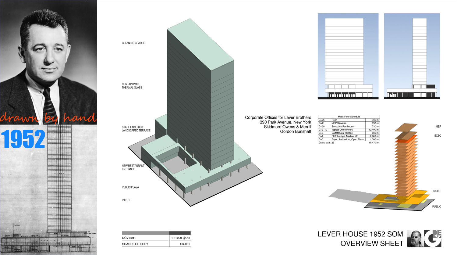
So this weekend I made a massing model of the Lever Building. When I visited this about 3 years ago, I was astounded at the condition it was in, but later discovered it had undergone a major refurbishment some 10 years previously. The building is almost exactly the same age as me and is a classic of its age. Pioneering use of curtain walling and suspended cleaning cradle. Piloti enable a generous plaza to be donated to the public realm. The main tower cantilevers some 3m beyond the column line to dramatise the separation of horizontal and vertical masses.

As always I gained new insights from the exercise and stumbled across new questions for further research. Just where is (or was) the auditorium ? Was it for staff or public use ? Does it still exist ? I have a section drawing showing one basement level, is this parking ? Which space was converted into a public restaurant in 2004? I now have some of the answers but I'll come back to that another time.
Gordon Bunshaft was born in Buffalo, location of the Larkin Mail-Order Soap Company. So he was almost the same age as another famous office building with social and environmental pretensions. I read a couple of weeks ago that Foster was doing open plan offices before they became fashionable. This may be so, but the soap companies were at it in the states 100 years ago.

Apparently Larkin pioneered all kinds of marketing techniques too, but the supermarkets destroyed their business around the time Lever House was being built, and Buffalo had Wright's building demolished in punishment for unpaid taxes.

Perhaps the folksy family marketing approach of Larkin was wiped out by the clinical strategies of modern multi-nationals like Unilever. The Larkin Building belongs to the days of innocence before World War I, Lever House to the brave new world after World War II when everyone was eager to sweep away the mistakes of the past.

Returning to my Revit model, a few observations on techniques used, nothing original. For the elevations I placed simple gradient jpegs directly in the view & cranked up the shadows to 75%. Isolating the mass floor faces in a view can be very effective. Here I selected individual faces and used overide by element to change the surface pattern to a different solid colour. This results in a very effective vertical zoning diagram. I also rounded off areas to the nearest 10 sq m under Project Units. Without this the schedule would display a misleading level of accuracy.

This is a good example of a situation where it is useful to have 2 versions of the same schedule. I just needed to summarise all the typical floors in a single line: easily achieved by un-ticking "itemize every instance" ... and then adding a comments field to give dummy labels to the floor levels.
In the final version most of the information is hidden, so a working schedule is very useful to cross-check that all the data is correct. Simple, but effective.
It would be nice if there were a more elegant way to achieve this. I am looking forward to the day when schedules are much more powerful and flexible. They are, after all, the "I in BIM" and surely deserve a more prominent and profficient role in the process.
I will finish with some 2d Drafting in preparation for making the curtain wall.

Aluminium curtain walls came in with the 70s. This one is all steel, and rather than a clear separation between structural frame and cladding as we would expect today, there seems to be a gradation. I have a very grainy construction photo showing horizontal angles and vertical channels following hard on the heels of the main frame. The angles also provide support for masonry infill (cinder blocks). It's an interesting sequence of operations.
I'm not sure what "heat resistant glass" means. In the 70s, when I was a bricklayer in the UK, "U" values were just starting to be taken seriously. I would like to know the spec of the glass used in the refurbishment. It doesn't look thick enough to be double-glazing, but is said to meet modern thermal standards.
I want to emphasize PROCESS: the activity of building. This is often neglected in construction textbooks, You get diagrams of Flemish Bond, and cross-sections through a finished window sills, but little sense of the physical activities that produce these end results. That's "the WAY we build."

Then there is "the way WE build." We all build differently. It may be climate, available materials, personal prejudice, expression of identity ... Whether you analyse the pyramids or a mud hut, the technology and the politics are inseparable.
So this weekend I made a massing model of the Lever Building. When I visited this about 3 years ago, I was astounded at the condition it was in, but later discovered it had undergone a major refurbishment some 10 years previously. The building is almost exactly the same age as me and is a classic of its age. Pioneering use of curtain walling and suspended cleaning cradle. Piloti enable a generous plaza to be donated to the public realm. The main tower cantilevers some 3m beyond the column line to dramatise the separation of horizontal and vertical masses.
As always I gained new insights from the exercise and stumbled across new questions for further research. Just where is (or was) the auditorium ? Was it for staff or public use ? Does it still exist ? I have a section drawing showing one basement level, is this parking ? Which space was converted into a public restaurant in 2004? I now have some of the answers but I'll come back to that another time.
Gordon Bunshaft was born in Buffalo, location of the Larkin Mail-Order Soap Company. So he was almost the same age as another famous office building with social and environmental pretensions. I read a couple of weeks ago that Foster was doing open plan offices before they became fashionable. This may be so, but the soap companies were at it in the states 100 years ago.

Apparently Larkin pioneered all kinds of marketing techniques too, but the supermarkets destroyed their business around the time Lever House was being built, and Buffalo had Wright's building demolished in punishment for unpaid taxes.

Perhaps the folksy family marketing approach of Larkin was wiped out by the clinical strategies of modern multi-nationals like Unilever. The Larkin Building belongs to the days of innocence before World War I, Lever House to the brave new world after World War II when everyone was eager to sweep away the mistakes of the past.

Returning to my Revit model, a few observations on techniques used, nothing original. For the elevations I placed simple gradient jpegs directly in the view & cranked up the shadows to 75%. Isolating the mass floor faces in a view can be very effective. Here I selected individual faces and used overide by element to change the surface pattern to a different solid colour. This results in a very effective vertical zoning diagram. I also rounded off areas to the nearest 10 sq m under Project Units. Without this the schedule would display a misleading level of accuracy.

This is a good example of a situation where it is useful to have 2 versions of the same schedule. I just needed to summarise all the typical floors in a single line: easily achieved by un-ticking "itemize every instance" ... and then adding a comments field to give dummy labels to the floor levels.
In the final version most of the information is hidden, so a working schedule is very useful to cross-check that all the data is correct. Simple, but effective.
It would be nice if there were a more elegant way to achieve this. I am looking forward to the day when schedules are much more powerful and flexible. They are, after all, the "I in BIM" and surely deserve a more prominent and profficient role in the process.
I will finish with some 2d Drafting in preparation for making the curtain wall.

Aluminium curtain walls came in with the 70s. This one is all steel, and rather than a clear separation between structural frame and cladding as we would expect today, there seems to be a gradation. I have a very grainy construction photo showing horizontal angles and vertical channels following hard on the heels of the main frame. The angles also provide support for masonry infill (cinder blocks). It's an interesting sequence of operations.
I'm not sure what "heat resistant glass" means. In the 70s, when I was a bricklayer in the UK, "U" values were just starting to be taken seriously. I would like to know the spec of the glass used in the refurbishment. It doesn't look thick enough to be double-glazing, but is said to meet modern thermal standards.


